

 en
en
 English
 русский
 Español
 عربى
عربى


HDPE Manufacturing: Processes, Quality Control & Cost Breakdown
Industry News-Content
- 1 What Is HDPE and How Is It Made?
- 2 Three Main HDPE Polymerization Processes
- 3 From Polymer to Pipe: The Extrusion Process
- 4 Key Quality Control Tests in HDPE Manufacturing
- 5 Cost Factors and Energy Consumption in HDPE Production
- 6 Common Defects and Troubleshooting in HDPE Processing
- 7 HDPE vs Other Plastics: Manufacturing Differences
- 8 Sustainability in HDPE Manufacturing: Recycling and Bio-Based Options
At 180 degrees Celsius, granular polyethylene resin transforms into a viscous melt that will soon become a 48-inch pressure pipe. That precise moment — when solid becomes fluid — dictates whether the final product lasts 50 years or fails within five. HDPE manufacturing is not a single technology. It is a series of interdependent chemical and mechanical decisions, each carrying cost and performance consequences that ripple through every inch of extruded product.
The global HDPE market consumed over 50 million metric tons of resin in 2025. Pipe applications alone account for roughly 18% of that volume. Behind every kilometer of installed pipe sits a manufacturing chain that begins with ethylene molecules and ends with hydrostatic pressure testing. Understanding that chain matters. It separates suppliers who deliver predictable performance from those who gamble with quality.
What Is HDPE and How Is It Made?
High-density polyethylene is a thermoplastic polymer produced from ethylene monomer through low-pressure catalytic polymerization. The resulting linear chains pack tightly, yielding a density range of 0.941 to 0.965 g/cm³. This structure gives HDPE its signature combination of stiffness, chemical resistance, and impact strength.
The manufacturing sequence breaks into three stages. First, ethylene gas is produced — typically through steam cracking of naphtha or ethane feedstocks. Second, polymerization occurs under controlled temperature and pressure with a catalyst system. Third, the polymer powder or pellets undergo compounding, pelletizing, and, for pipe-grade material, classification under ASTM D3350.
The raw inputs include:
- Ethylene monomer (99.9% purity minimum for pipe-grade resin)
- Comonomer (1-butene or 1-hexene, 0.5-2% by weight for controlling density and crack resistance)
- Ziegler-Natta, chromium-based, or metallocene catalyst
- Stabilizer packages: antioxidants, UV absorbers, carbon black (2-2.5% for outdoor pipe applications)
The basic polymerization reaction chains ethylene molecules into long macromolecules under pressures typically below 5 MPa. By the time that reaction completes, the polymer's molecular weight distribution, branching frequency, and crystallinity are already set — locked-in characteristics that no downstream extrusion process can significantly alter.
Three Main HDPE Polymerization Processes
Not all HDPE resin starts the same way. Three dominant reactor technologies produce the resin that eventually becomes pipe, film, or injection-molded parts. Each process operates under distinct conditions, uses different catalysts, and delivers polymer with specific property profiles. The choice of process directly affects molecular weight distribution, comonomer incorporation, and long-term performance under load.
The gas-phase process runs at 80-110 °C and 0.1-2 MPa, typically using Ziegler-Natta or metallocene catalysts on a fluidized bed. It produces a broad range of melt index products with medium-to-wide molecular weight distribution. Slurry processes operate at lower temperatures (70-90 °C) and similar pressures (0.3-1 MPa), using Ziegler-Natta or chromium catalysts in a hydrocarbon diluent. These yield narrower molecular weight distributions, which suit pipe resins requiring high Environmental Stress Crack Resistance (ESCR). Solution processes push temperatures to 150-250 °C at 3-5 MPa, dissolving the polymer in solvent for the narrowest molecular weight distribution and the best control over comonomer placement.
| Parameter | Gas Phase | Slurry | Solution |
|---|---|---|---|
| Temperature (°C) | 80-110 | 70-90 | 150-250 |
| Pressure (MPa) | 0.1-2 | 0.3-1 | 3-5 |
| Catalyst Type | Ziegler-Natta, Metallocene | Ziegler-Natta, Chromium | Ziegler-Natta, Metallocene |
| Melt Index Range (g/10min) | 0.01-100 | 0.01-50 | 0.5-100 |
| MWD (Molecular Weight Distribution) | Medium-Broad | Medium | Narrow |
| Typical Pipe Application | General-purpose water, conduit | Gas distribution, high-ESCR pipe | High-performance pressure pipe |
For buried pressure pipe applications — where slow crack growth resistance defines service life — slurry-produced resins with chromium catalysts dominate. The bimodal molecular weight distribution achieved in modern slurry reactors delivers the optimal balance: a high-molecular-weight fraction for strength and ESCR, plus a low-molecular-weight fraction for processability. This combination explains why PE4710 and PE100 resins overwhelmingly use slurry-loop or slurry-cascade reactor systems.
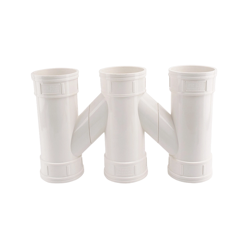
Choosing the right resin grade involves matching the polymerization process output to the final product requirements. A pipe designed for municipal water distribution benefits from narrow-MWD solution-grade resins that minimize gels and ensure consistent wall thickness. Products like PVC pipeline systems serve different niches but face analogous raw-material-to-performance translation challenges.
From Polymer to Pipe: The Extrusion Process
Once the resin powder leaves the polymerization plant — stabilized, compounded with carbon black masterbatch, and pelletized — it enters the extrusion line. The goal sounds simple: melt the pellets, shape the melt into a tube, cool it, and cut it to length. Execution is anything but simple.
The extrusion line consists of five integrated zones: feed, melting, metering, die forming, and cooling. A single-screw extruder with a length-to-diameter ratio of 30:1 or 33:1 gradually heats the resin from ambient to 180-230 °C across multiple barrel zones. The screw design — compression ratio, barrier flights, mixing sections — determines melt homogeneity and throughput stability.
The standard extrusion sequence:
- Resin pellets and masterbatch are gravity-fed into the hopper, often with a dryer (dew point -40 °C minimum) removing residual moisture.
- Barrel heating zones bring the material to 180-230 °C; screw rotation (typically 20-100 rpm, depending on pipe diameter) shears and mixes the melt.
- The molten polymer passes through a screen changer (mesh size 60-120) to remove gels and contaminants before entering the die head.
- A spiral mandrel die distributes the melt evenly around the circumference, forming the pipe wall at a die gap calibrated to 1.05-1.20 times the final wall thickness.
- The hot tube enters the vacuum calibration sleeve, where external water spray (15-25 °C) and internal air pressure (0.02-0.05 MPa) set the final dimensions.
- Pullers draw the pipe at a constant speed synchronized with extruder output; wall thickness gauges provide real-time feedback.
- A planetary saw or guillotine cutter sections the pipe to length without deforming the cut face.
Temperature control at each barrel zone matters more than any single parameter. A deviation of 10 °C in the metering zone can shift melt viscosity enough to create wall-thickness variation exceeding 5%. For large-diameter pressure pipes used in municipal water systems, that variation directly reduces the pipe's pressure rating at constant safety factor.
Extrusion lines producing HDPE corrugated drainage pipe — such as double-wall designs for stormwater management — add a corrugator that forms the outer profile while a liner die shapes the smooth inner wall. The two layers fuse while still above the melting point, creating an integral structure. Products in this category, including PPR water supply systems, demonstrate how multi-layer extrusion technologies enable performance characteristics not achievable with single-material designs.
Key Quality Control Tests in HDPE Manufacturing
Resin makers and pipe extruders alike live by standardized test methods. ASTM D3350 is the classification backbone for polyethylene pipe materials. It defines a cell system that codes density, melt index, flexural modulus, tensile strength, slow crack growth resistance, and hydrostatic strength classification into a six-digit-plus-letter code like PE445574C — meaningless to outsiders, indispensable to engineers specifying pipe for 50-year service.
Five tests form the core quality framework:
| Test | ASTM Method | Typical Range (Pipe Grade) | Common Failure Cause |
|---|---|---|---|
| Melt Index (MI) | D1238 (190 °C, 5.0 kg) | 0.1-0.8 g/10min | Inconsistent catalyst feed, degradation |
| Density | D1505 / D792 | 0.945-0.960 g/cm³ | Comonomer ratio drift, cooling rate variance |
| Tensile Strength at Yield | D638 (Type IV, 50 mm/min) | 23-30 MPa | Crystallinity too low, oxidative degradation |
| Environmental Stress Crack Resistance (ESCR) | D1693 (Condition B, 100% Igepal) | >500 hours (PE4710: >1,000 h) | Low MW fraction, insufficient comonomer |
| Hydrostatic Strength (LTHS) | D2837 / D1598 | MRS 8-10 MPa | Brittle fracture initiation, pipe defects |
Hydrostatic testing deserves special attention. Pipe samples are subjected to internal pressure at elevated temperatures (typically 80 °C) for thousands of hours. The resulting stress-rupture curves determine the Minimum Required Strength (MRS) that feeds directly into the pipe's pressure rating. A PE4710 compound must demonstrate 1,000-hour hydrostatic strength exceeding 10 MPa at 20 °C, verified across multiple production lots. This long-term validation separates pipe-grade resins from general-purpose HDPE.
On the factory floor, in-line quality monitoring adds a second layer. Ultrasonic wall-thickness gauges scan continuously. Gravimetric feeding systems track resin consumption against output to catch density shifts. For every 8-hour shift, operators pull samples for melt-index verification and visual inspection. The cost of skipping these checks? One undetected gel contamination event can create a stress concentration that reduces pipe burst pressure by 15-20%.
Cost Factors and Energy Consumption in HDPE Production
Ethylene monomer dominates the cost structure. At typical North American ethane-based cracker economics, ethylene represents 60-70% of total HDPE production cost. Catalyst and additives contribute 5-10%. Energy — encompassing steam, electricity, and cooling water — accounts for 10-15%. The remaining portion covers labor, maintenance, and logistics.
Process technology choice shifts these proportions. Gas-phase plants invest less upfront capital but consume 10-15% more electricity per ton due to the energy required to fluidize and recirculate the gas bed. Solution plants, with their solvent recovery systems, carry higher operating costs but produce premium-grade resins commanding a 5-8% price differential. Slurry-loop processes sit in the middle, offering the lowest variable cost per ton for commodity pipe-grade output.
The cost differentials by process route:
- Gas phase: Lowest CapEx ($800-$1,000 per annual ton of capacity), moderate OpEx
- Slurry loop: Medium CapEx ($1,000-$1,200/ton), lowest OpEx for single-grade pipe resin
- Solution: Highest CapEx ($1,200-$1,500/ton), highest OpEx, premium product pricing potential
For a pipe extruder purchasing resin on the open market, these upstream cost structures translate into price volatility driven by ethylene contract prices and supply-demand balance. Forward-thinking buyers structure contracts with ethylene-indexed formulas, accepting quarterly price resets in exchange for consistent material supply and grade stability.
Common Defects and Troubleshooting in HDPE Processing
Even with properly classified resin, extrusion can go wrong quickly. The most frequent defects share root causes that are diagnosable through systematic observation and measurement. Understanding the cause-effect chain transforms a production line stoppage from a crisis into a solvable problem.
| Defect | Symptoms | Root Cause | Corrective Action |
|---|---|---|---|
| Melt Fracture / Sharkskin | Rough, matte surface; periodic ridges perpendicular to flow | Shear stress at die exit exceeds critical value (typically >0.14 MPa) | Increase die/melt temperature by 5-10 °C; reduce line speed; add polymer processing aid (PPA) |
| Bubbles / Voids in Wall | Internal spherical voids visible in cut section | Moisture in resin (>0.02% by weight); volatiles from degraded additive | Check dryer dew point (<-40 °C); increase barrel zone 1 temperature to vent volatiles early |
| Wall-Thickness Variation | Eccentricity >5% of nominal; high/low spots around circumference | Uneven die gap; mandrel offset; inconsistent melt temperature distribution | Re-center die mandrel; verify die heater band function; reduce screw speed to stabilize melt flow |
| Surface Roughness / Orange Peel | Fine surface texture, uniform but visually irregular | Cooling rate too rapid; melt temperature too low; die-lip sticking | Reduce quench water flow or raise temperature to 25-30 °C; polish or plate die lips |
| Brittle Failure in Impact Test | Pipe shatters rather than deforms under drop weight | Crystallinity too high due to slow cooling; resin degradation from overheating | Increase cooling rate in calibration zone; verify barrel temperature profile (no hot spots) |
The most cost-effective troubleshooting step is also the most overlooked: measuring melt temperature at the die exit with a needle probe thermometer. Barrel thermocouple readings often differ from actual melt temperature by 5-15 °C. Without this direct measurement, adjustments based on barrel readings alone can push the process further from optimal conditions. Experienced operators develop a feel for the correlation — but data beats intuition every time.
HDPE vs Other Plastics: Manufacturing Differences
HDPE shares processing equipment with other thermoplastics, but the similarities end at the extruder hopper. Polypropylene (PP) processes at lower temperatures (200-240 °C vs HDPE's 200-250 °C melt, though HDPE requires higher die temperatures). PVC demands entirely different screw materials (stainless steel or chrome-plated) and adds the complexity of thermal stabilizers to prevent degradation. Even between these three commodity materials, the line cannot simply switch resins without a purge procedure that consumes 1-3 hours and hundreds of kilograms of transitional material.
| Parameter | HDPE | PP (Homopolymer) | PVC (Rigid) |
|---|---|---|---|
| Extrusion Melt Temp (°C) | 180-230 (die) | 200-240 | 170-200 |
| Cooling Rate Sensitivity | High (affects crystallinity) | Moderate | Low (amorphous) |
| Mold Shrinkage (%) | 1.5-3.0 | 1.0-2.5 | 0.2-0.6 |
| Chemical Resistance (Acids) | Excellent | Good-Excellent | Good |
| Screw Material Requirement | Nitrided steel | Nitrided steel | Stainless or chrome-plated |
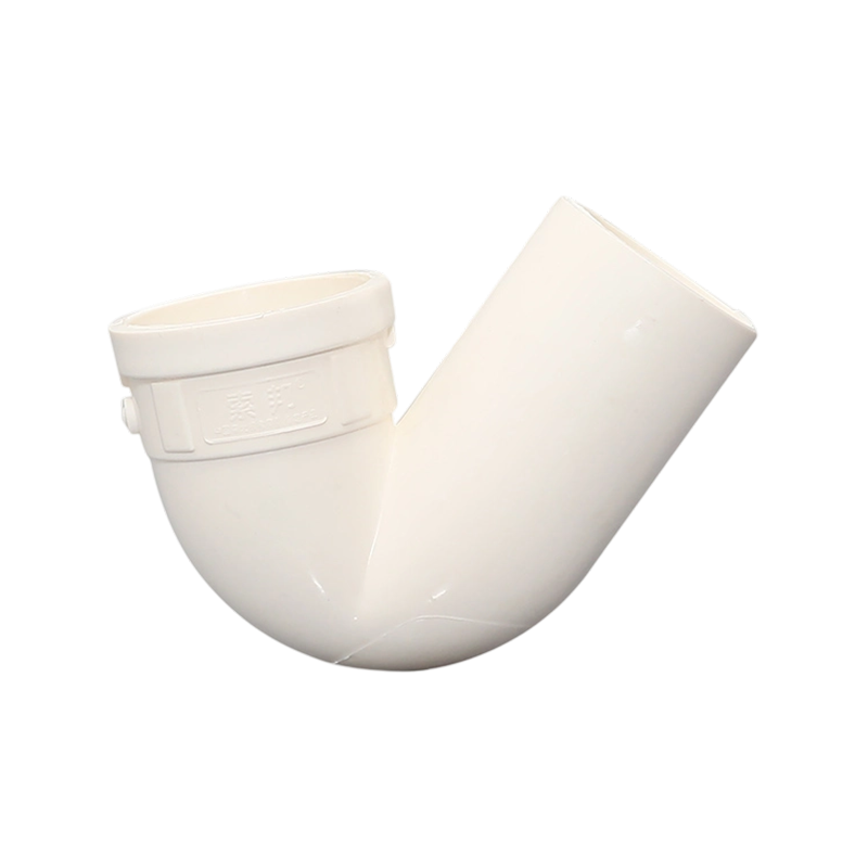
For pipe applications specifically, HDPE's semi-crystalline nature demands slower, more controlled cooling than PVC. Rapid quenching in cold water (below 15 °C) freezes the outer surface into a low-crystallinity skin while the interior continues to crystallize. The resulting density gradient creates residual stresses that can reduce long-term pressure resistance. PVC avoids this through its amorphous structure. PP, also semi-crystalline, shares HDPE's sensitivity but to a lesser degree due to faster crystallization kinetics. When specifying pipe for drainage applications, understanding these processing differences helps explain why PVC traps and fittings maintain dimensional stability with simpler post-extrusion handling than equivalent HDPE components.
Sustainability in HDPE Manufacturing: Recycling and Bio-Based Options
The carbon footprint of fossil-based HDPE runs roughly 1.8-2.0 kg CO₂ equivalent per kg of resin, from cradle to pellet. About 75% of that falls in feedstock production and polymerization. The remaining quarter tracks energy consumption during extrusion and conversion. Every percentage point of recycled content directly subtracts from that baseline.
Post-industrial and post-consumer HDPE recyclate blends into virgin material at inclusion rates up to 30% for non-pressure pipe applications (conduit, drainage, corrugated pipe). Beyond that threshold, impact strength and ESCR degrade measurably. Key quality shifts for 70/30 virgin/recyclate blends: melt index increases by 5-15%, tensile strength at yield drops by 3-8%, and ESCR F50 failure time can decrease by 20-40%. Processing adjustments — specifically increasing extruder barrel temperature by 5-10 °C in the melting zone — compensate for the higher melt viscosity variability of mixed-feed streams.
Bio-based HDPE, produced from sugarcane ethanol dehydrated to ethylene, claims a negative cradle-to-pellet carbon footprint (roughly -2.0 kg CO₂/kg resin due to sugarcane's CO₂ absorption during growth). The polymer properties are chemically identical to fossil-based HDPE. The trade-off: cost. Bio-based HDPE commands a 30-50% premium over conventional grades, limiting adoption to brands willing to pay for carbon neutrality claims. A more pragmatic path for most manufacturers combines 20-30% post-industrial recyclate with optimized process energy management — cutting both material cost and Scope 3 emissions simultaneously.
Our Product //
Recommend Products
 +86-13801995968
 +86-18017886575
 No. 366, Lane 6995, Puxing Road, Fengxian District, Shanghai
Copyright © SHANGHAI PILSA PIPE INDUSTRY CO., LTD. All rights reserved.

